
Why snow load matters for PV planning
PV systems add modules, mounting systems, ballast, maintenance zones and local load areas to an existing roof. In snowy regions or on flat roofs, teams need a clear view of which areas are geometrically suitable and what information the structural engineer needs.
Snow-load design belongs to Eurocode EN 1991-1-3 and national annexes. A photogrammetry model does not replace that calculation, but it improves the geometric basis for it.
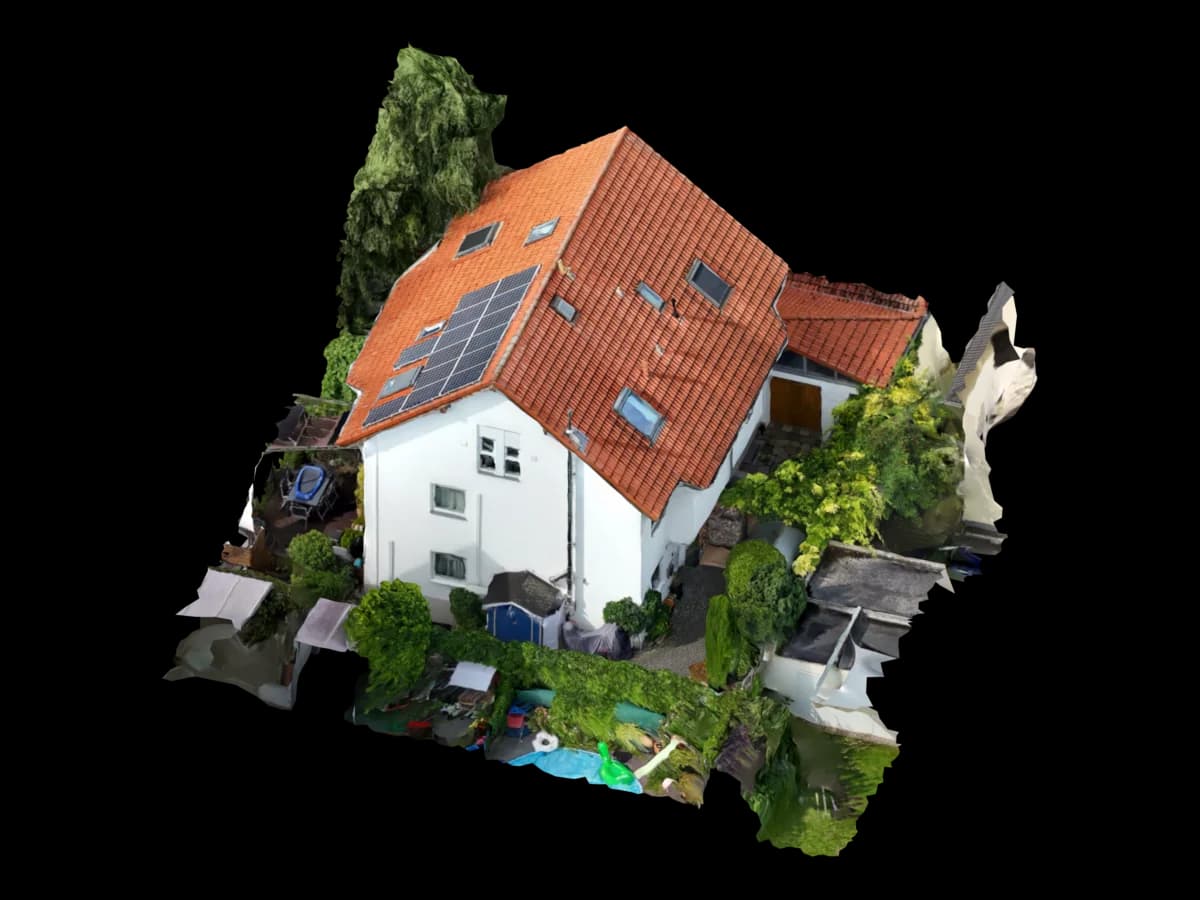
What a 3D roof model reliably provides
The useful output is not just a visual model. It is measurable roof geometry, obstacles, parapets, height changes, orthophotos, CAD traces and viewer states that help all parties discuss the same roof reality.
| System / dataset | Suitability | Best for | Practical note |
|---|---|---|---|
| Roof pitch and orientation | Basis for module layout and roof-form context | Pitched, flat and complex existing roofs | Sub-areas can be reviewed separately. |
| Parapets and obstacles | Identify exclusion, maintenance and coordination zones | Commercial and refurbished roofs | Viewer markers make critical areas easy to discuss. |
| Orthophoto and CAD trace | Planning-ready 2D deliverable | PV layout, takeoff and engineering questions | DXF/DWG reduces breaks between imagery, CAD and PV software. |
| 3D viewer | Coordination without specialist software | Client, solar team, roofer and engineer review | Open questions can be marked spatially. |
Which data PV layout and engineering need
A useful deliverable clarifies measurable areas, obstacles, exclusion zones, reference level and coordinate context. Material data, roof build-up, support structure and PV mounting details do not come from imagery alone and must be supplied separately.
Typical risks on existing roofs
Old drawings, single photos and rough satellite imagery are often too weak for dependable coordination. Flat roofs with parapets and older commercial roofs need particular care.
| Risk scenario | Why it matters | Typical symptom | Countermeasure |
|---|---|---|---|
| Assumed roof pitch | Real pitch affects layout and snow movement context | Layout needs rework after site review | Derive pitch and sub-areas from the model. |
| Missing parapets or obstacles | They affect module spacing, access and local coordination | Late redesign or installation conflict | Map visible obstacles in orthophoto, CAD and viewer. |
| Structural request without clear geometry | Engineers need understandable load and area zones | More questions and slower approval | Send roof model, CAD file and exclusion zones together. |
| Incomplete imagery | Hidden edges and missing oblique views weaken reconstruction | Gaps or unclear edges | Review the image set before processing. |
Workflow from supplied images to planning data
The process is about data preparation: review the image set, reconstruct geometry, derive planning outputs and document limitations.
Review imagery and target output
Check whether edges, obstacles and roof areas are visible enough for CAD, orthophoto, viewer or PV delivery.
Create the 3D roof model
Build a textured model or point cloud and prepare visible geometry for planning.
Derive planning data
Export roof areas, edges, obstacles and exclusion zones as orthophoto, DXF/DWG or viewer data.
Document limits
Name unclear areas and parameters that cannot be derived from imagery.
Limits: what Voxelia does not replace
Snow-load design, load assumptions, structural reserve, materials, mounting systems and approvals must be handled by qualified professionals. Voxelia supports the visible geometry and delivery.