
Why fall protection is a 3D topic
Roof fall protection becomes concrete when people actually need access: solar installation, maintenance, cleaning, waterproofing, inspection or repair. Single photos and rough plans rarely show all relevant edges, rooflights, openings, service paths and height changes.
For the DACH market, DGUV Information 201-056 provides a current planning context for selecting roof fall protection systems. Voxelia does not replace safety planning; it turns supplied imagery into measurable roof geometry for better coordination.
What the 3D roof model clarifies
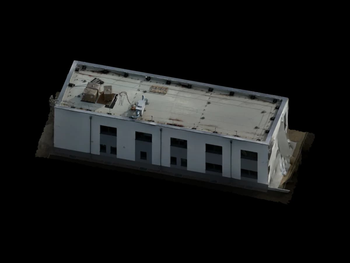
A 3D roof model shows where risks and coordination issues appear: open edges, roof openings, rooflights, level changes, parapets, technical equipment and narrow paths between PV modules.
The model is strongest before installation. Solar planners, roofers, safety coordinators and building operators can review the same spatial base instead of interpreting separate photos and drawings.
Planning data that matters
Useful imagery must capture safety-relevant areas: roof edges, access points, openings, technical obstructions, roof pitch, PV areas and possible zones for fall protection systems.
A 3D model can prepare distances, zones and open issues. Final values and system decisions must be checked against regulations, manufacturer data and project requirements.
| Use case | Formula / Logic | Best for | Limit |
|---|---|---|---|
| Identify roof edges | Edge + opening + height change | Make risk areas visible in the model | Risk evaluation needs specialist assessment. |
| Prepare restraint zones | Work area must not reach the fall edge | Early geometric plausibility check | System data and deflection must be checked per project. |
| Review PV service paths | Array + access + movement area | Coordinate solar layout and later maintenance | Required widths and measures depend on the project. |
| Structure the CAD delivery | Layers for edges, openings, paths and zones | Clean transfer to CAD and BIM workflows | Layers are not installation approval. |
Workflow: from imagery to safety context
Start with the user and decision: solar layout, service access, roof repair, operator documentation or safety coordination. This defines the necessary model detail and export format.
Voxelia checks coverage, sharpness, metadata, scale references and visibility before creating the model and delivery.
Clarify goal and users
Solar teams, roofers, operators and safety coordinators need different detail levels.
Review imagery
Edges, openings, access points, parapets and obstructions must be visible.
Create 3D model and orthophoto
Imagery becomes measurable geometry, roof orthophoto, point cloud or mesh.
Mark zones and paths
Edges, service paths, possible restraint areas and open issues are added as layers or viewer markers.
Export the delivery
CAD, viewer, screenshots, orthophoto or BIM-adjacent data are delivered with assumptions and limits.
Deliverables for roofing, solar and planning
A strong delivery separates geometry from safety approval. Voxelia delivers model geometry and structured data; specialists decide the protection concept.
Early coordination often works well in a viewer. CAD layers, orthophotos and BIM-adjacent models are better for technical continuation.
| Delivery | Useful for | Watch out |
|---|---|---|
| 3D viewer with zones | Fast coordination between operator, roofer, solar team and planner | Shows assumptions, not approved protection. |
| Roof orthophoto | Review edges, equipment, openings and PV layout in top view | Height and hidden areas need 3D context. |
| DXF/DWG layers | CAD work with edges, paths, obstructions and zones | Coordinate reference and layer logic must be documented. |
| BIM-adjacent delivery | As-built records, owner documentation and recurring maintenance | LOD/LOIN should be defined upfront. |
Limits, responsibility and sources
Fall protection is safety-critical. A model improves spatial understanding, but it cannot approve the protection concept, installation, substrate, fixing system, inspection or user instruction.
Use the model as geometry input, then validate the safety decision with the applicable regulations, manufacturer documentation and qualified professionals.