
Why scaffold planning benefits from 3D data
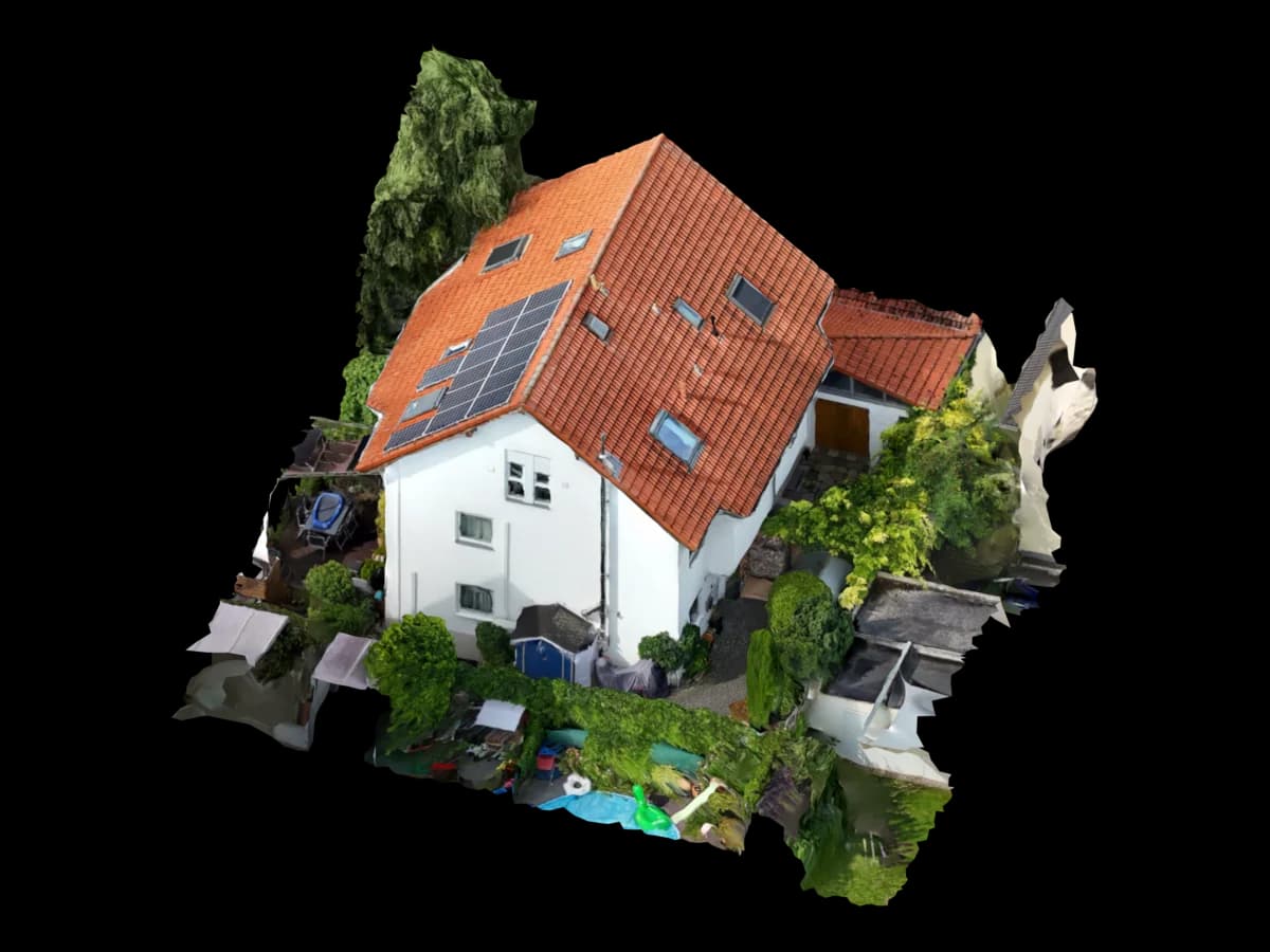
Scaffold requests need more than facade photos. Teams need building height, facade length, roof edges, projections, balconies, terrain steps, access, storage areas and the exact work zones.
Official German guidance separates responsibilities across clients, planners, scaffold contractors and users. A 3D model can improve the basis for discussion, but it does not replace scaffold design, assembly instructions or inspection.
Voxelia supports the preparation phase. We process supplied imagery into spatial foundations so contractors and planners can coordinate with clearer geometry.
What a 3D model clarifies before scaffolding
A 3D as-built model makes the building envelope measurable and discussable. Facades, roof edges, parapets, dormers, balconies and terrain become visible in one shared scene.
This is useful when roofers, solar installers and facade contractors need to coordinate access and work zones on existing buildings.
Scaffold system providers increasingly describe model-based and BIM-supported planning. The as-built model is the input, not the substitute for specialist planning.
Important data for scaffold planning
The model contributes as-built geometry. Real scaffold planning adds system data, load classes, use case, anchoring concept, assembly sequence, ground conditions, access routes and inspections.
For preparation, lengths, heights, edges, terrain offsets and work zones are the most useful communication values.
| Use case | Formula / logic | Best for | Limit |
|---|---|---|---|
| Facade takeoff | Scaffold length ≈ facade section + corner/work allowances | Request, quantity overview and early variant review | System grid and execution details belong to the scaffold contractor. |
| Height review | Working height = relevant building edge + work zone | Roof edges, parapets and PV work areas | Protective measures depend on rules and specialist planning. |
| Terrain offset | ΔH = setup area A - setup area B | Early detection of difficult access and setup areas | Load transfer and support require professional planning. |
| Obstacles | Facade + projections + roof overhang + exclusion zones | Make balconies, canopies and attachments visible | Anchoring and system details must not be guessed from imagery. |
Workflow: from imagery to scaffold context
The workflow starts with the decision to support: scaffold request, takeoff, roof renovation, PV installation, facade work, logistics or BIM coordination.
Useful imagery shows facades, roof edges, terrain, access and obstacles from multiple angles. Existing plans or reference measurements improve the delivery.
Clarify affected elevations
Define which facade, roof edge or work zone is relevant and who will use the output.
Review imagery and references
Check coverage, sharpness, overlap, metadata, scale and visible obstacles.
Create as-built geometry
Generate mesh, point cloud, orthophoto or simplified CAD geometry depending on the goal.
Mark scaffold-relevant zones
Identify facade sections, height points, roof edges, access areas and obstacles.
Prepare the delivery
Prepare viewer, DXF/DWG, orthophoto, point cloud, IFC-oriented export or screenshots.
Useful deliverables for scaffolders and planners
A strong delivery package documents model state, scale, data source, visible assumptions and open issues.
Early coordination may only need a viewer. CAD or BIM workflows may need DXF/DWG, point cloud, orthophoto or IFC-oriented data.
| Deliverable | Useful for | Watch out |
|---|---|---|
| 3D viewer with markers | Coordination between client, scaffolder, roofer, solar team and site management | Communication model, not approved scaffold design. |
| DXF/DWG facade context | Facade sections, roof edges, height points and CAD review | Document layers, scale, origin and accuracy assumptions. |
| Orthophoto or orthoplane | Facade takeoff and visible component positions | Occlusions, glass and repetitive surfaces can limit processing. |
| Point cloud or mesh | Spatial review of projections, terrain and roof/facade transitions | Visual density is not the same as survey accuracy. |
Limits, safety and responsibilities
Scaffolds are safety-relevant temporary structures. Planning, erection, use, inspection and control have separate responsibilities.
3D context is valuable on existing buildings with incomplete plans, tight courtyards, overhangs, balconies, slopes, PV retrofits and facade renovation.
Voxelia provides the data basis: 3D models, CAD geometry, orthophotos and viewer scenes from imagery. Execution, engineering, anchoring and approval remain with qualified specialists.