
Why control points turn imagery into planning data
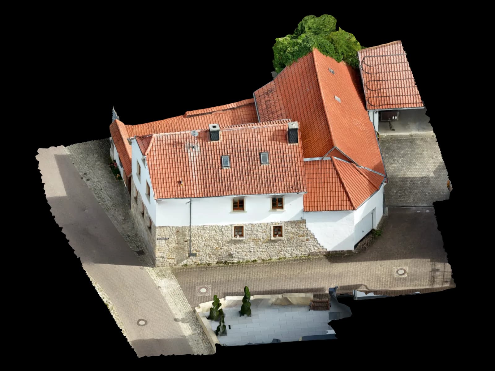
Photogrammetry derives geometry from image overlap. Without additional references, a model may look convincing while scale, position, and independently checked areas remain unclear.
Voxelia processes supplied roof, building, facade, and site imagery into useful 3D models, orthophotos, CAD/BIM bases, and planning data. Good point information makes that processing more dependable.
Control point, checkpoint, and manual tie point are different roles
A control point or GCP has known coordinates or a known reference. It can support scale, position, and orientation.
A checkpoint is kept independent and compared after reconstruction. Manual tie points connect the same image feature across photos but do not provide real-world scale by themselves.
| System / dataset | Suitability | Best for | Practical note |
|---|---|---|---|
| Control point / GCP | stabilizes position and scale | orthophotos, CAD bases, survey-oriented deliveries | Provide coordinates, point name, coordinate system, and image marking. |
| Checkpoint | independent review | acceptance, model QA, CAD/BIM sign-off | Keep it out of calculation to preserve its control value. |
| Manual tie point | improves image linking | weak overlap, repeated facade patterns, difficult edges | Helpful for matching, but not proof of real-world scale. |
| Local reference distance | local scaling | roof details, facade sections, photos without GNSS | Several distances are better than one edge measurement. |
Which point data should be supplied
Useful inputs include original photos with EXIF data, a CSV or TXT point list, sketches or screenshots showing point locations, coordinate system notes, reference measurements, and the intended output.
If no measured points exist, building elements can sometimes serve as local references: roof edges, parapet segments, module rows, door openings, window axes, or marked targets.
Typical errors in supplied images and points
Many datasets fail because points are unclear, not because software is weak. A point on a shadow edge, a blurry target, or a mark interpreted differently in each image is not a dependable control.
Using all measured points as GCPs also removes independent checking. Then the report can look stronger than the delivery really is.
| Risk scenario | Why it matters | Typical symptom | Countermeasure |
|---|---|---|---|
| Checkpoint used as GCP | The point is no longer independent | Reported deviations look artificially low | Define review points before processing |
| Ambiguous image point | The clicked location shifts between images | unstable edges or local deformation | Use sharp, high-contrast, hard corners or targets |
| Missing coordinate system | Position reference is unclear | CAD/GIS import lands incorrectly or only locally | Provide coordinate system, unit, and origin |
Voxelia workflow for reviewable imagery
The workflow starts with the decision the output must support. A viewer has different requirements than DXF/DWG, BIM reference data, GeoTIFF orthophotos, or PV planning.
Define the output
Viewer, mesh, orthophoto, point cloud, CAD, BIM-oriented delivery, or PV model set the required review level.
Sort point roles
GCPs, checkpoints, tie points, and reference measurements are separated, named, and checked for visibility.
Validate reconstruction
Edges, roof planes, facade planes, point distribution, and weak zones are inspected.
Label the delivery clearly
The output is marked as locally scaled, georeferenced, checked, or visual-only where appropriate.
What CAD, BIM, and orthophoto workflows need
CAD needs clear units, useful layers, traceable edges, and coordinate context. BIM workflows need to know whether the model is a reference mesh, point cloud, component basis, or issue context. Orthophotos need an honest statement on georeferencing or local scale.
Voxelia turns supplied imagery into a usable data state with the right export, visible limitations, and a clear path into CAD, BIM, PV, or viewer workflows.